Three fun electronics projects
Here are three electronics projects you can put together and play with in very little time, with no soldering required. Everything you need can be purchased at the supermarket, hardware store, Radio Shack or your local dollar store. Many of the components are shared among projects, so you can tear down one circuit and try out the next without having to buy a lot of new parts. And if you already have similar kinds of components, feel free to use them.
Stringing Parts Together
To wire up these gadgets, we’ll use a “breadboard,” which lets you string circuits together easily. To get an idea of how it works, place it in front of you with the length facing left and right. The holes in each vertical column above the middle are connected to each other. The holes in each column below the middle are also, except for the very top and bottom rows, which are separated from the other holes. Those are connected lengthwise across the entire board, and are not connected to the holes above and below them.
Chips, or integrated circuits (ICs), are the square, black plastic items with eight legs. They look like robot bugs. They are pressed into the board at the middle, with four leads on the top half of the board, and four on the bottom half. This arrangement lets you connect wires and other parts to the chips’ leads by pressing the wires and other leads into the holes on the same column. Those very top and bottom rows are used for the positive (+) and negative (-) leads from the battery pack, so you can tap off them anywhere along the length of the board and connect them to whatever columns require connection to the battery.
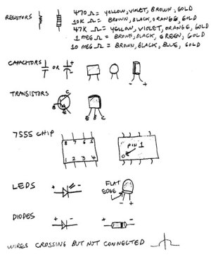 The chips have pins (legs) labeled 1 through 8. With the legs facing down, look for a dot or a dimple in one corner of the chip. That’s pin 1. Turn the chip so that pin 1 is in the lower left corner. The rest of the pins are numbered counterclockwise around the chip in a ring, with pin 8 directly above pin 1.
Other parts we’ll use are transistors, resistors, capacitors, batteries, a battery holder, a speaker and an LED (light-emitting diode). Each part has a “schematic” symbol that indicates what it does but doesn’t look like the actual part. (See the list of schematic symbols to the right, click to enlarge.) We’ll use schematic diagrams, which show the concept of how the circuit is connected, and also drawings called “pictorials” that look like the real thing when it’s on the breadboard.
To connect a part to a pin on the chip, just press the part’s lead into any available hole on that pin’s column. To link a pin to another pin, or to one of the top and bottom rows for the battery connections, you need a short piece of insulated solid wire that’s stripped at both ends, called a “jumper wire.” Make up a dozen or so by cutting some solid hookup wire, Radio Shack #278-1222 or similar, into 3-inch pieces and then stripping about ¼ inch of insulation off each end.
OK, let’s build something!
SUPER-SENSITIVE CURRENT DETECTOR
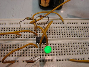 Everybody knows paper doesn’t conduct electricity. Or does it? Many materials that we consider insulators actually conduct very tiny amounts of current. Here’s a circuit that can detect current flow so small that even expensive laboratory meters can’t see it. An LED blinks if there’s any current flow at all. The faster the blinking, the more current is flowing. The smallest amounts of current most normal meters can detect will blink this circuit’s LED so fast that it will appear to be on solidly. This thing is sensitive! You’ll have fun connecting it to books, bed sheets and just about anything else you can think of that isn’t obviously conductive. The results will surprise you.
The circuit works by storing in the capacitor the tiny amount of current flowing through whatever you’re testing. The electricity gets stored like water in a cup, with the voltage rising as more is put in. When the voltage gets high enough, the chip detects it and turns on the LED, while also quickly draining the charge from the capacitor. As soon as the charge is gone, the light goes out and the process starts over again. The more current that flows through your object, the faster the capacitor charges up and the faster the light flashes.
What You’ll Need
- Breadboard, Radio Shack #276WBU301
- 7 jumper wires made from solid hookup wire, Radio Shack #278-1222 or similar
- 4 clip leads
- TLC555CP timer chip, Radio Shack #276-1718
- 100 pf (picofarad) capacitor, Radio Shack #272-123
- 1 MΩ (megohm, or million ohms) resistor, Radio Shack #271-1356
- 10 MΩ resistor, Radio Shack #271-1365
- LED, Radio Shack #276-304 or similar. Any small LED will work.
- Battery holder, Radio Shack #270-383
- 4 AA alkaline batteries
What You’ll Do
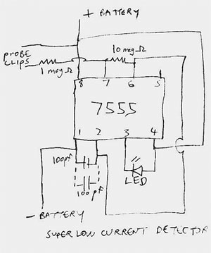
1. Turn the chip so that the dimple for pin 1 is in the lower left corner. Position it over the center of the breadboard, and press its pins into the holes until you feel it snap in.
 Resistors use bands of color instead of numbers to show their values. The 1 MΩ (megohm) resistor’s bands are brown, black, green, gold. The 10 MΩ resistor’s bands are brown, black, blue, gold. They’re similar, so be careful not to confuse them. If you do, the circuit won’t work right, but you won’t hurt anything.
2. Connect the parts as shown in the drawings. When you plug in the LED, be sure the shorter lead (from the flat edge of the case) goes to pin 3 of the chip. Connect two clip leads as shown to use for connecting to whatever you want to test. It’s best not to use red and black leads for these because we’ll use those colors for the battery connections.
3. Put the batteries in their holder with their flat, negative ends going to the springs, and connect a red clip lead to the smaller terminal on top. Now connect a black clip lead to the larger terminal. Connect the leads’ other ends to the upper- and lower-most holes on the breadboard, the ones that connect from left to right, using jumper wires. The red clip goes to the top row on the board, and the black one goes to the bottom. Be certain not to get this backward, or you will probably ruin the chip.
4. The light might blink a time or two, but then it should stop. Now hook the loose ends of the test probes onto something non-metallic. Try a sheet of paper first. Take your hands off the test probes, because touching them can fool the circuit and make it blink when it shouldn’t.
Does the light blink? With most paper, it will. Even long stretches of paper conduct enough current for this circuit to detect it. Try clipping to two separate sheets of paper, and then lay one on top of the other. Use a drinking straw or the eraser end of a pencil to press one paper onto another. Just a small area of contact will blink the light because a very tiny current is flowing. Now try other household items. Stay away from electrical wiring or anything else that could be dangerous.
Troubleshooting
If the light won’t blink, you probably have an incorrect connection on the breadboard, the LED is in backward or the battery is not hooked up correctly. Disconnect one of the battery’s leads and check the wiring, and also check that you have the resistors in the right places. Then hook the battery back up. Grabbing the free ends of the test probes should turn the light on.
If the light blinks when the probes aren’t connected to anything, be sure you’re not touching them or their wires, and that their free ends aren’t touching something that could be conductive. Even a tabletop may show some current flow.
DOORKNOB TOUCH DETECTOR
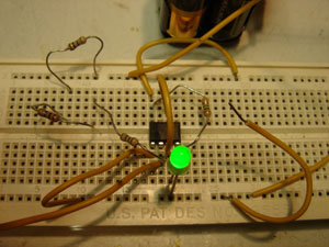 Ever wonder if anybody has been in your room while you were away? Here’s a circuit that turns on the LED if your doorknob has been touched. It uses the same chip but wired differently.
The circuit works by detecting the electrical noise our bodies pick up from the nearby AC power wiring. When that noise gets to the doorknob through somebody’s hand, the circuit senses it and turns on the light, keeping it on until you reset it.
What You’ll Need
- Breadboard
- 7 jumper wires
- 3 clip leads
- TLC555CP timer chip
- 1 MΩ resistor
- Three 10 MΩ resistors
- LED
- Battery holder and batteries
What You’ll Do
1. Wire the circuit as shown in the diagrams. This one uses the same 1 MΩ resistor, but it also needs a 30 MΩ resistor, and those aren’t easy to get! To make one, string three 10 MΩ resistors together in series, one after the other. This time, the flat side of the LED connects to the bottom row of holes, the one that goes to the negative battery terminal via the black clip lead.
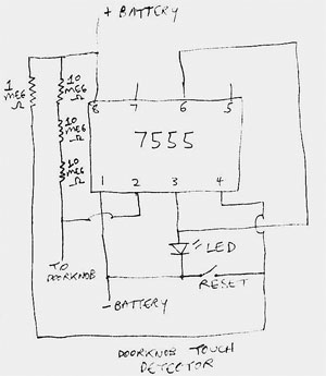 2. To connect to the doorknob, unscrew one of the knob assembly’s screws on the inside of the door, just a little. Strip the insulation off the ends of about 4 feet of hookup wire. Push one end under the screw and then tighten it back up. Connect the other end to pin 2 of the chip. Connect the battery, being sure that the negative (black) lead goes to the bottom of the board and the positive (red) lead goes to the top, the same as it did with the last project.
3. The light will probably turn on. See the loose wire connected to the bottom row? Touch it for a moment to the resistor lead coming from pin 4 of the chip. That resets the circuit and turns off the light. Let it hang loose again. Now grab the doorknob, and the light should come on. It will stay on until you reset the circuit again.
4. To get into your room without setting off the circuit, wear a glove or use a towel or washcloth to turn the doorknob. Even a paper towel or napkin might do the trick, depending on the electrical noise level of your house. Experiment to see what works.
Troubleshooting
If nothing happens, check for errors in the circuit’s wiring. Be sure the LED’s flat side goes to the bottom row of holes.
Different locations have varying amounts of electrical noise. If the circuit keeps turning itself on when nobody is touching the doorknob, try making the detector less sensitive by reducing the 30 MΩ resistor to 20 MΩ. Remove one of the 10 MΩ resistors and connect the remaining two to each other.
If the circuit won’t turn on at all, or it does sometimes and not others, increase the sensitivity by adding another 10 MΩ resistor to the string, for a total of 40 MΩ. The more resistors, the more sensitive the detector will become, but too many will make it turn on when it shouldn’t.
QUICK-DRAW GAME
 Who’s quicker on the draw, you or your friends? Which hand reacts faster, your right or your left?
This project has two levers made from Popsicle sticks and two LEDs. After a tone sounds, press your lever as fast as you can and hold it down. Whoever hits it faster lights his LED and locks out the other person’s LED from lighting. The tone stops until both levers are released. After a short delay, it turns back on, and the fun starts all over again.
The circuit uses the timer chip as a tone generator, along with two transistors for the lever-pressing detector.
What You’ll Need
- Breadboard
- 10 jumper wires (or more, depending on how you lay out the circuit)
- 6 clip leads
- TLC555CP timer chip
- Two 2N3904 transistors, Radio Shack #276-2016
- Two 1N4148 diodes, Radio Shack #276-1122
- Two 10 KΩ (kilohm, or thousand ohms) resistors, Radio Shack #271-1335
- 1 MΩ resistor
- Two 470 Ω resistors, Radio Shack #271-1317
- Two 47 KΩ resistors, Radio Shack #271-1342
- 2 LEDs
- 22 µf (microfarad) capacitor, Radio Shack #272-1026
- 1 µf capacitor, Radio Shack #272-1055
- 0.1 µf capacitor, Radio Shack #272-1053 or 272-1069
- Speaker, Radio Shack #273-0092
- Two Popsicle sticks
- Stapler
- Piece of wood or cardboard
- Two cotton swabs
- Battery holder and batteries
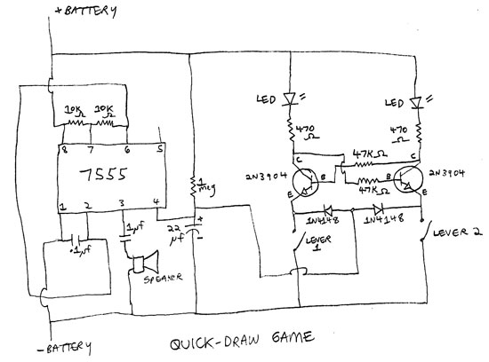
What You’ll Do
Wire the circuit as shown in the diagrams. Be especially careful to orient the transistors correctly. Their three leads, E (emitter), B (base) and C (collector) have to be connected to the right places, or the circuit won’t work. Also make sure that the bands on the diodes go to the E terminals on the transistors. The flat sides of the cases on the LEDs go to the 470 Ω resistors. Finally, take care that the vertical line on the 22 µf capacitor goes to the negative connection to the battery, not to the chip.
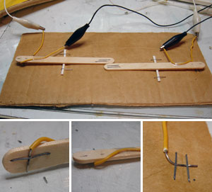 To make the levers, staple the ends of four jumper wires, two to the Popsicle sticks and two to the wood or cardboard base, as shown. Use pliers to flatten the sharp points of staples coming out of the Popsicle sticks. Put some tape around the lever wires, so they won’t work loose. Cut off the cotton ends of two swabs and put the sticks crosswise, around the middle of the levers. Staple those down, and also staple the ends of the levers to the base, being sure that the staples for the wire contacts hit each other when the lever is pressed. Check that the distance between the switch end of the lever and the base is the same for both levers. If not, adjust the swab stick on one until the distances match. If you choose a cardboard base, use a screwdriver to press the sharp ends of the staples down flat, and put some tape over them so they won’t scratch the furniture when you play the game.
Using clip leads, connect the wires from the lever base, one to each E lead of the transistors. Connect both wires from the levers themselves to the bottom row of breadboard holes, the ones that go to the negative battery lead.
Connect the battery pack and wait a few seconds for the tone. When it sounds, hit and hold a lever. The corresponding LED will light, and pressing the other lever will not light its LED. When an LED lights, the tone will stop. After you let go of the levers, the tone will come on again in a few seconds. As soon as you hear it, whack your lever!
Troubleshooting
If nothing happens, check carefully for wiring errors. Be sure the 22 µf capacitor isn’t backward. If an LED won’t light, check that its shorter lead faces the 470 Ω resistor. If the LEDs light but the tone won’t stop, be sure the bands on the diodes go to the E terminals on the transistors. If the LEDs won’t light but the tone keeps playing, check that the staple contacts on the levers touch when the levers are pressed.
cool project!
cool